Schematics
- PlayuavOSD schematic – Schematic and layout
Wired
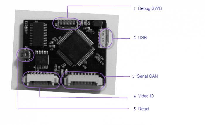
Please refer to the below hardware instructions. The input is classified into video input and data input. Data transmission varies according to the types of flight controllers, specifically, some data is transmitted via serial port while others via CAN. Output can also be classified into video output and data output, both are connected to the video transmitter.
Connectors
Pinouts
SWD port(From right to left 1,2,3,4,5)
| Pin | Signal | Volt |
|---|---|---|
| 1 | VCC | +5V |
| 2 | GND | GND |
| 3 | SWDIO | |
| 4 | SWCLK | |
| 5 | NRST |
Serial CAN port(8 pins: from left to right 1,2,3,4,5,6,7,8)
| Pin | Signal | Volt |
|---|---|---|
| 1 | GND | GND |
| 2 | CANH | |
| 3 | CANL | |
| 4 | Reserved | |
| 5 | Reserved | |
| 6 | TX(OUT) | |
| 7 | RX(IN) | |
| 8 | VCC | +5V |
Video IO(7 pins: from left to right 1,2,3,4,5,6,7)
| Pin | Signal | Volt |
|---|---|---|
| 1 | Video 2 signal | |
| 2 | Video 2 GND | GND |
| 3 | Video 1 signal | |
| 4 | Video 1 GND | GND |
| 5 | Video out signal | |
| 6 | Video out GND | GND |
| 7 | Audio out |
